
Updated: 10/23/2017
Pls download and reinstall the latest driver and the issue will be resolved.
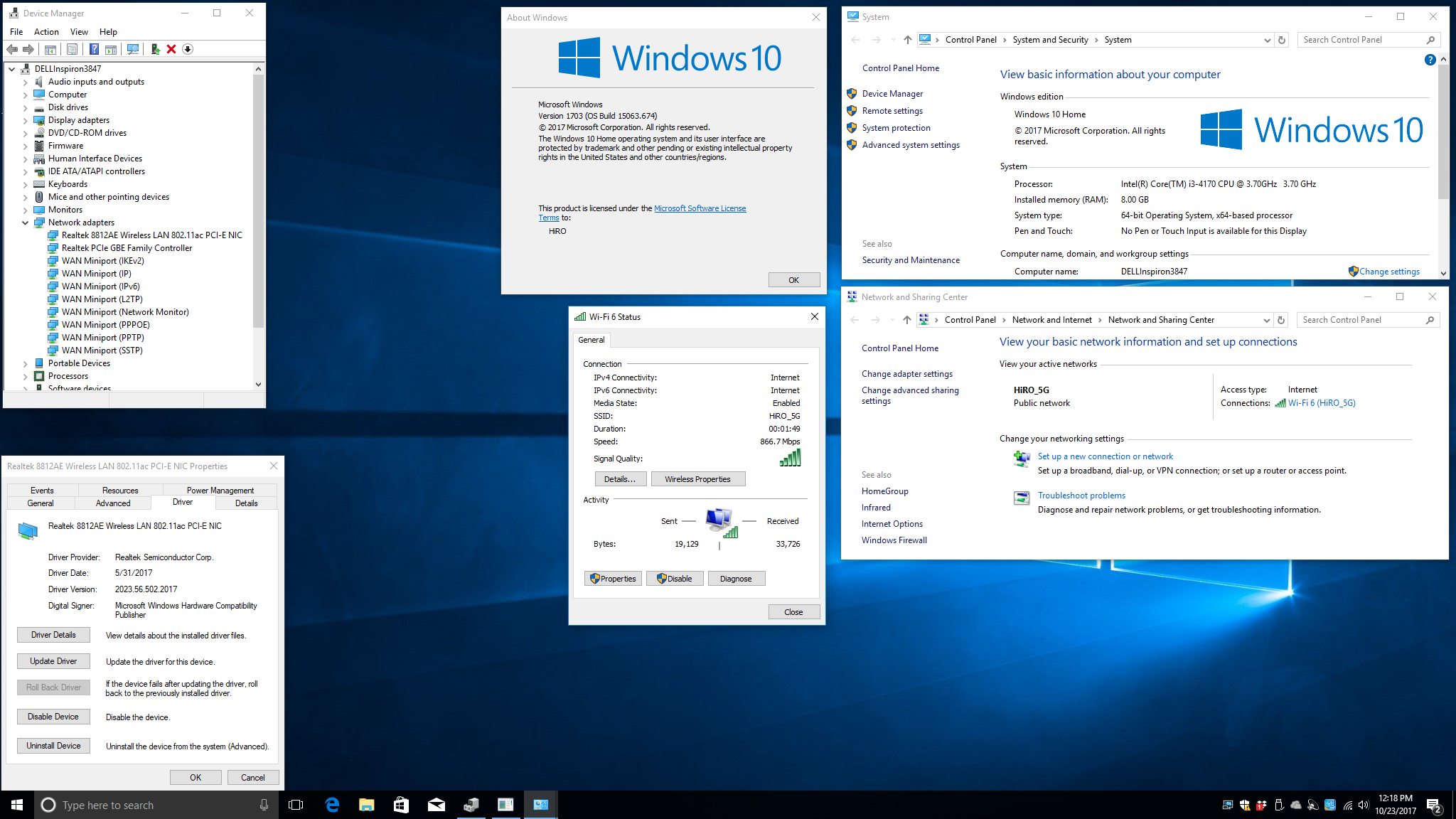
Issues:
Device becomes malfunction w/ exclamation mark. Driver version remains no change 2023.43.914.2016
Cause:
Driver issue, an old driver was reinstalled when a new driver is present.
1. Device is plug n play under Windows 10
3. Windows update updated driver to 2023.43.914.2016
4. If user reinstall driver from CD after driver was updated by Windows update to 2023.43.914.2016, device becomes malfunction w/ exclamation mark. Driver version remains no change 2023.43.914.2016
Solution:
Manually roll back or reinstall driver to the previous version 2023.23.1030.2015 and then update the driver to the latest one 2023.43.914.2016
1. Device is plug n play under Windows 10

3. Windows update updated driver to 2023.43.914.2016

4. If user reinstall driver from CD after driver was updated by Windows update to 2023.43.914.2016, device becomes malfunction w/ exclamation mark. Driver version remains no change 2023.43.914.2016

read more
H50113 External USB Modem Driver roll back to 2.2.98 after update to 2.2.102
https://www.youtube.com/watch?v=36kTOEJcZvI
Open Device Manager (from control panel or right click on Computer then click Manage then double click Device Manager)
Double click on
Modems then right click on the device
and choose Update Driver Software
Click on "Browse my computer for driver software"
Choose "Let me pick from a list of device drivers on my computer"
Click "Have disk"
Click "Browse"
Select lsimu64v (for Win 10 64-bit) or correspond .inf file from the file folder that you downloaded from http://www.hiroinc.com/drivers/H50113/
Click "OK"
You will find only one modem under " Install new modem", click on next
Installing Driver Software (done)
read more
You can do this using the Windows Update service. Via Control Panel > Administrative Tools, you can access Services. In the Services window, scroll down to Windows Update and turn off the process. To turn it off, right-click on the process, click on Properties and select Disabled. That will take care of Windows Updates not being installed on your machine.
read more

To setup an account under Windows Fax and Scan, pls follow the instruction below.
1. Open Windows Fax and Scan
2. Click "Tools"
3. Click "Fax Accounts"

4. Click "Add"

5. Click "Connect to a fax modem"

6. Click "Next"

7. Choose one of the following options

8. Account is now added

Pls download the latest driverread morehttp://www.hiroinc.com/drivers/H50228/ Pls manually install driver by following the instruction belowhttp://www.hiroinc.com/drivers/H50228/H50228%20Manually%20Install%20Driver.pdf
You can install the driver by following instruments below:
1. Go to Control Panel and open Device Manager.
2. Right click the device you’d like to update driver and select properties.
3. Select Driver tab, then click the Update Driver button.
4. Choose Browse my computer for driver software.
5. Choose Let me pick from a list of device drivers on my computer
6. Click Browse and locate the .inf driver file from the driver folder you extract. Click Open and Next.
7. The driver will be installed.
There is also a video clip guiding you to manually install driver step by stephttp://www.hiroinc.com/drivers/H50228/H50228%20Win10%2064-bit%20Dell%20Inspiron%203847%20Manually%20Install%20Driver.mp4


